Project Title: Improvement of transmission line protection system against lightning strikes
Supported by:
Impact Oriented Interdisciplinary Research Grant Programme (IIRG001B-2020IISS), Universiti Malaya
Synopsis:
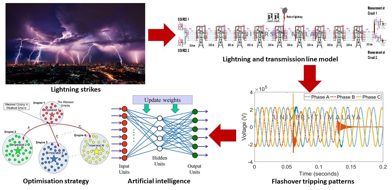
Lightning flashover has been identified as the major weather-related events of overhead transmission line tripping in Malaysia. Improving the transmission line protection against lightning is crucial to avoid physical damage to the system equipment, which could result in power supply interruptions to consumers. Although various lightning protection systems are already in place, significant number of tripping due to lightning strikes sill happen in Malaysia. Therefore, in this project, improvement of transmission line protection system against lightning strikes is conducted to overcome the existing solutions. The flashover patterns on transmission line system due to lightning for mitigation techniques are evaluated. Then, transmission line protection systems for effective flashover mitigation are designed. The optimal lightning arrester placement on transmission line for lightning protection advancement is determined. Finally, the transmission line lightning protection capability between different flashover mitigation strategies are compared for identifying the most effective protection technique.
Methodology

About Lightning
Lightning is a visible discharge of static electricity between ground and cloud, between clouds or within a cloud. It has been one of the problems for insulation design of power systems and it is still the main cause of transmission and distribution lines outages. Malaysia, having a very high number of lightning days per year, at 220 days per year and recorded flash density of 20 flashes/km/year typically experiences overvoltages due to lightning strikes. Transmission line faults due to lightning strikes cause serious damages, such as massive blackout and instantaneous voltage drop on electric power systems.
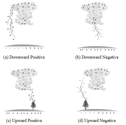
Generally, flashes that lower positive charges to ground are specified as positive lightning, while those that transfer negative charges to ground are referred to negative lightning. Due to their initiating leader process, they are further classified into upward and downward lightning.
Downward lightning is characterised into two types. The positive downward lightning has a positive downward leader, while the negative downward lightning has a negative downward leader, as depicted in Figure 1(a) and (b). This leader is propagating down from the thundercloud towards ground to discharge lightning. Structures or buildings up to about 100 m are often struck by this type of lightning.
When the downward propagating leader approaches ground, the electric field at grounded objects increases due to the charge contained in the downward leader channel. As soon as the electric field exceeds a certain level, connecting leaders start from the grounded objects, making the finals connection between the objects at ground and the downward leader. This is the beginning of the return stroke phase, where the return stroke current flows through the struck object.
Figure 1(c) and (d) show another type of lightning discharge, which is upward lightning for positive and negative upward leaders. For this type of lightning, the leader initiates from the top of the structure or building and increases the electric field. To exceed the critical electric field strength, the structure or building must have a height of about 100 m at minimum.

Figure 1: Types of cloud to ground lightning discharge (Uman, M.A. (2001). The Lightning Discharge: Dover Publications)
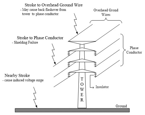
Lightning flashovers at transmission lines are divided into three types; lightning that strike on a phase conductor, on an overhead ground wire, or to nearby ground. Figure 2 shows the summary of transmission line failures caused by lightning strikes. Flashover that occurs from the lightning strike to ground wire is called back flashover while for lightning strike directly to phase conductor is called shielding failure flashover.

Figure 2: Summary of modes of failure caused by a lightning strike
Protection of Transmission Lines Against Lightning
In order to ensure the continuity of supply to consumer, several protection methods have been introduced to improve the lightning performance. These include adding ground wires, reducing tower footing resistance, increasing the insulation and installing line surge arresters.
Line surge arrester is a device installed on transmission lines of a power system network to reduce the probability of flashover during lightning and switching surge events. The protective device, which is usually installed between the phase conductor and earth acts as insulation during normal operating conditions. The arrester main functions are to divert the lightning to the ground, clamp the voltage induced by the lightning before returning to its original state and only protects equipment electrically parallel with it. The arrester develops a discharge voltage across its terminal, which is a function of the magnitude and wave shape of the discharge current wave, arrester design and voltage rating. After the lightning surge current has been discharged, a correctly installed surge arrester is capable to repeat its protective function until another surge voltage has to be discharged.
It is important to understand the behaviour of the surge arrester when it is stressed by overvoltage with different wave shapes and amplitudes. Various studies have been conducted to determine the best location and placement of the arrester to minimise system momentary outage. The arrester must be installed at every tower or pole to be effective at preventing shielding failure flashovers. The use of surge arresters in lightning protection of overhead transmission lines is to improve reliability of electric utilities. However due to the economic reasons, it is not possible to install surge arresters at each transmission structure of overhead transmission line. Hence, proper selection of surge arrester placement can provide the optimum solution to major lightning problems and result in economical installation cost.
Project Impact:
To Electric Utility:Gallery:

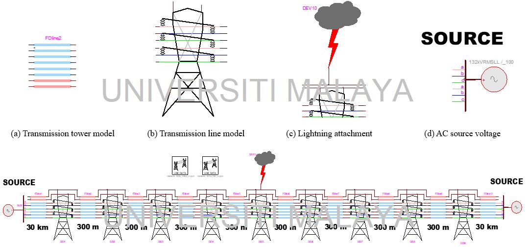
Figure 3: Transmission line model
Last Update: 16/08/2024